

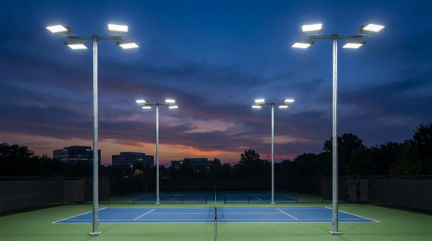
Flood Light Pole
Steel, stainless steel, or aluminum flood light poles configured for parking areas, sports facilities, industrial sites, and commercial lighting. Structural capacity, finish, ingress protection, and wind design are confirmed according to the selected luminaires and project specification.
Specifications
The specifications below describe galvanized steel anchor-base options. Final luminaire components, electrical ratings and compliance documents depend on the selected model. Custom heights and wattages for projects exceeding 50 units are subject to review against the approved project design.
- Pole Height
- Pole Material
- Shaft Profile
- Wall Thickness
- Base Plate
- Anchor Bolts
- LED Module
- Driver
- Input Voltage
- Power Factor
- THD
- Color Temperature
- CRI
- Beam Angles
- Surge Protection
- Operating Temp
- Certifications
- 12m / 18m / 25m / 30m / 35m / 40m
- Q345B High-Strength Steel, Hot-Dip Galvanized
- 12-sided tapered polygonal (OD 180–380mm)
- 6.0mm – 20.0mm (height dependent)
- 500×500mm – 800×800mm, 20–30mm thick
- M24 – M42, Grade 8.8, hot-dip galvanized
- Philips 3030 / Lumileds 5050 / CREE XB-H
- Inventronics / Mean Well HLG series
- AC 100–277V / 347–480V (50/60Hz)
- > 0.95 at full load
- < 10%
- 4000K / 5000K / 5700K
- > 70 (standard) / > 80 (optional)
- 15° / 30° / 60° / 90° / Asymmetric
- 10kV / 20kV (line-line & line-ground)
- -40°C to +55°C
- Model- and market-specific; request applicable test reports before ordering
Every part is engineered for durability, serviceability, and ease of installation in the field.
LED Flood Light Head
The floodlight model, beam distribution and mounting angle are selected from the approved luminaire data sheet and lighting layout. Confirm fixture weight and projected area before finalizing the pole design.
Multi-Arm Mounting Bracket
The number of arms, outreach, mounting connections and aiming layout are specified for the selected luminaires. Bracket design is reviewed against fixture loads and site wind criteria.
Tapered Pole Shaft
The tapered shaft provides the structural support and internal cable path. Shaft dimensions, access-door location, fabrication details and finish are confirmed on the approved project drawing.
Foundation Base Assembly
The base plate and anchor-bolt pattern are coordinated with the pole loads and foundation design. Grounding, cable-entry and installation details are confirmed on the approved drawing.
Engineered for Extreme Conditions
Material selection, finish system, drainage details and maintenance access are coordinated for the project environment. For coastal or salt-exposed sites, review the corrosion-protection considerations before specifying the pole.
Light output, efficacy and wattage depend on the selected floodlight model and its test documentation. Modular luminaire options can be reviewed against the required lighting layout and maintenance plan.
Hot-dip galvanizing can be specified for steel pole shafts. The applicable standard and coating thickness are confirmed in the approved manufacturing specification and inspection records; coastal exposure may require additional protection review.
Ingress- and impact-protection ratings depend on the selected floodlight model, not the pole alone. Confirm the required IP and IK ratings from the luminaire data sheet and test documentation for the project environment.
Bracket layout, the number of floodlight heads, aiming range and adjustment method are specified for the selected fixtures and structural design. Share the luminaire weight, projected area and required beam layout for review.
Control options such as 0–10V, DALI or wireless systems can be reviewed for compatible luminaires and project requirements. Receptacle type and wiring details are confirmed in the approved fixture and pole drawings.
The luminaire housing, heat-sink design, ambient-temperature rating, and lumen-maintenance performance are confirmed from the selected fixture data sheet and relevant test documentation. Pole structural design uses the actual fixture weight and projected area.
Flood Light Pole Applications
Flood light pole configurations can be developed for sports facilities, parking areas, industrial yards, transport sites and other outdoor lighting projects. Final geometry and structural inputs are confirmed from the approved project specification.
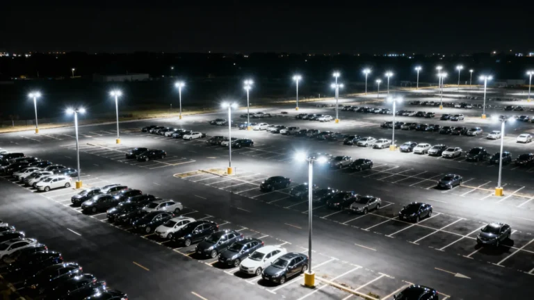
For parking areas, logistics yards and industrial sites, pole placement and luminaire distribution are evaluated against the project lighting plan. Asymmetric optics can help manage spill light when selected and aimed appropriately.
Flood Light Pole FAQs
What information is needed to specify a flood light pole?
Share the site location, required mounting height, luminaire quantity, fixture weight and projected area, arm outreach, installation method, and applicable wind or structural criteria. A lighting layout and foundation information help confirm the pole configuration.
Does the specification table apply to aluminum and stainless steel poles?
No. The table describes galvanized steel anchor-base options. Aluminum and stainless steel configurations require their own approved material, shaft, finish, and foundation details.
How are floodlight and pole ratings confirmed?
Use the selected luminaire data sheet and relevant test reports to confirm electrical, optical, IP, IK, and compliance details. Confirm shaft dimensions, fixture loads, base plate, and anchor details in the approved structural drawings.
Can the floodlight arrangement be customized?
The number and position of luminaires can be reviewed against the lighting plan, fixture loads, and site wind criteria. Final bracket and pole details are confirmed before production.
- Deep Design & Engineering Support
- CAD & Technical Drawings
- 3D Renderings & Visualization
- Prototyping & Sampling
- Flexible Manufacturing (OEM & ODM)
- Street Lighting & Roadway Poles
- Commercial & Residential Landscape Lighting
- High Mast Poles for areas, ports, and stadiums
- Decorative & Architectural Poles for urban beautification projects
- Solar Light Poles